DAR ALMAHIREENTECHNICAL SERVICES L.L.C
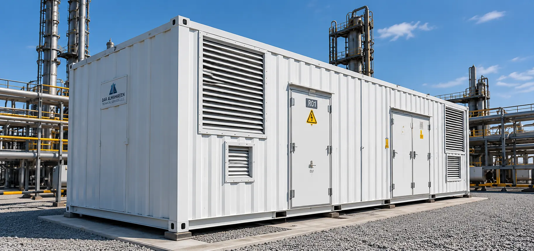
White containerised technical room with louvres and personnel doors at a process plant

03 / Industrial & Technical

Engineered Spaces for Demanding Industrial Operations

Explore purpose-configured technical units for electrical systems, industrial equipment, workshop activities and specialist offshore applications. Each solution can be developed around the project's equipment layout, operating conditions and technical requirements.

  • Flexible Configurations
  • Durable & Weather-Ready
  • Built for Industrial Performance
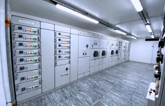
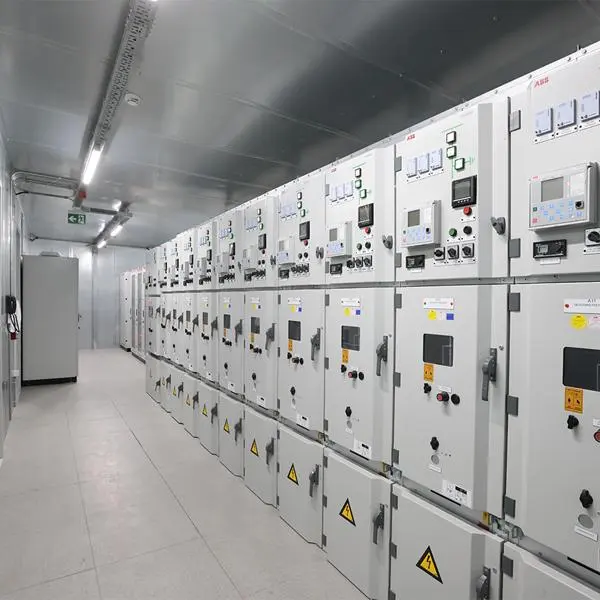
Electrical switchgear room

1 / 3 · Electrical room

01

Electrical & Control Rooms

Dedicated Space for Critical Electrical Systems

Our modular electrical and control rooms provide a controlled, organized environment for electrical distribution, instrumentation and automation systems. Unit layouts can be developed around cabinet dimensions, operating clearances, cable routes, equipment heat loads and maintenance requirements.

Typical applications: Electrical rooms · Local Equipment Rooms (LER) · Local Control Rooms (LCR) · PLC and instrumentation rooms

Available design formats

Base formatExternal dimensions: L × W × HTypical layout approach
20 ft standard6,058 × 2,438 × 2,591 mmCompact single-room arrangement
40 ft standard12,192 × 2,438 × 2,591 mmLonger cabinet line and access space
40 ft high cube12,192 × 2,438 × 2,896 mmAdditional nominal height for services
Custom-built moduleAs designedProject-specific footprint and height
Detailed technical specifications
ItemTechnical specification / configuration
Main structureEngineered steel frame or modified container structure, designed for the finished unit and its loads
Structural materialSteel grade and section sizes selected through structural design
External wallsWeather-resistant steel enclosure or engineered insulated wall assembly
Internal wall finishSuitable lining selected for the operating environment and required fire performance
RoofWeather-resistant construction with insulation and drainage provisions as required
InsulationType and thickness selected from thermal, condensation and fire requirements
FlooringLoad-rated floor designed for equipment point loads and maintenance access
Equipment mountingEngineered cabinet bases, supports and anchoring arrangements
Personnel doorSize, swing and hardware selected for access and escape requirements
Equipment accessRemovable panels or larger openings where cabinet installation requires them
Electrical supplyVoltage, phase, frequency and available fault level defined by project electrical data
DistributionMain and auxiliary distribution arranged according to connected loads
EarthingProtective earthing and bonding according to the electrical design
Cable routingFloor or wall entries, cable trays and segregated routes as required
LightingGeneral, task and emergency lighting according to the room design
HVACCapacity calculated from equipment heat rejection, ambient conditions and envelope heat gain
VentilationProvided where required by the equipment and cooling strategy
Fire protectionDetection, alarm and suppression provisions according to the project fire assessment
MonitoringTemperature, humidity or other monitoring where specified
External coatingSurface preparation and coating system selected for site exposure
Transport and liftingEngineered for the completed unit's weight and centre of gravity
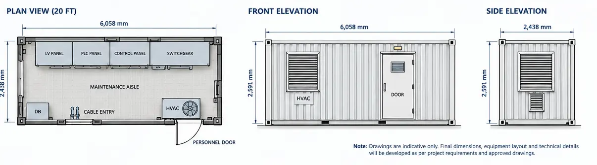
Electrical & control room: indicative plan view, front elevation and side elevation of a 20 ft unit
Drawings are indicative only. Final dimensions, equipment layout and technical details will be developed as per project requirements and approved drawings.
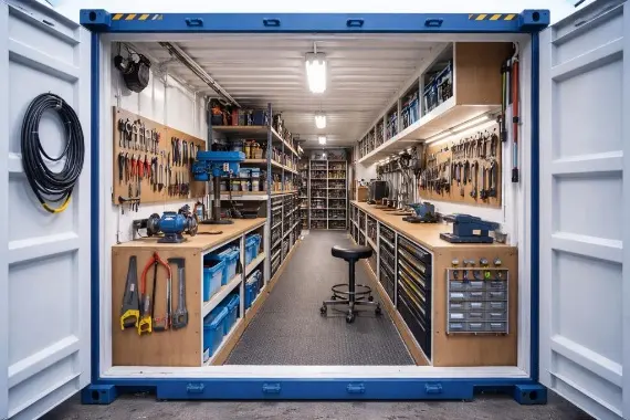
Container workshop with workbench, tool wall and cabinets

02

Industrial Workshop Units

Practical Workshop Space, Configured Around Your Work

Our industrial workshop units bring work surfaces, organized tool storage and essential utilities together in a compact modular format. Layouts can be configured for maintenance, assembly, inspection and project support activities, with equipment provisions selected for the intended work.

Typical applications: Maintenance workshops · Tool rooms · Mechanical assembly areas · Project support units

Size options

Base formatExternal dimensions: L × W × HTypical layout approach
20 ft standard6,058 × 2,438 × 2,591 mmWorkbench and storage arrangement
40 ft standard12,192 × 2,438 × 2,591 mmExtended working and storage areas
40 ft high cube12,192 × 2,438 × 2,896 mmAdditional nominal height
Custom-built moduleAs designedLayout for specific tools and equipment
Detailed technical specifications
ItemTechnical specification / configuration
Main structureEngineered steel frame or modified container structure
External enclosureWeather-resistant wall and roof construction
Internal finishDurable lining selected for the work environment
InsulationSelected according to climate, occupancy and project requirements
FloorLoad-rated, durable finish suitable for tools, benches and equipment
WorkbenchesDimensions, surface material and load capacity selected for intended tasks
Tool storageCabinets, drawers, shelving and retention provisions as specified
Equipment mountingDedicated supports or reinforced bases where required
Personnel accessDoor size and hardware suited to personnel movement
Equipment accessLarger doors or removable panels where required
WindowsOptional, subject to the approved layout
Electrical supplySelected from tool and equipment connected loads
Distribution boardCircuits and protective devices according to electrical design
Socket outletsQuantity, location and rating based on equipment schedule
LightingGeneral and task lighting for work surfaces
VentilationDesigned for occupancy and any process-generated heat or contaminants
HVACSelected according to climate, occupancy and internal heat loads
ExtractionLocal extraction where required by the specific work process
Fire and safetyProvisions based on the actual activities and fire-risk assessment
CoatingProtective external finish selected for site exposure
Transport and liftingBased on completed-unit weight and approved handling arrangement
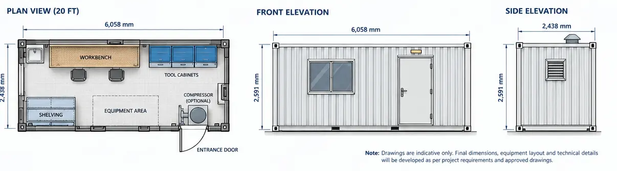
Industrial workshop unit: indicative plan view, front elevation and side elevation of a 20 ft unit
Drawings are indicative only. Final dimensions, equipment layout and technical details will be developed as per project requirements and approved drawings.
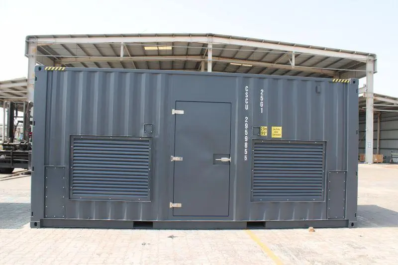
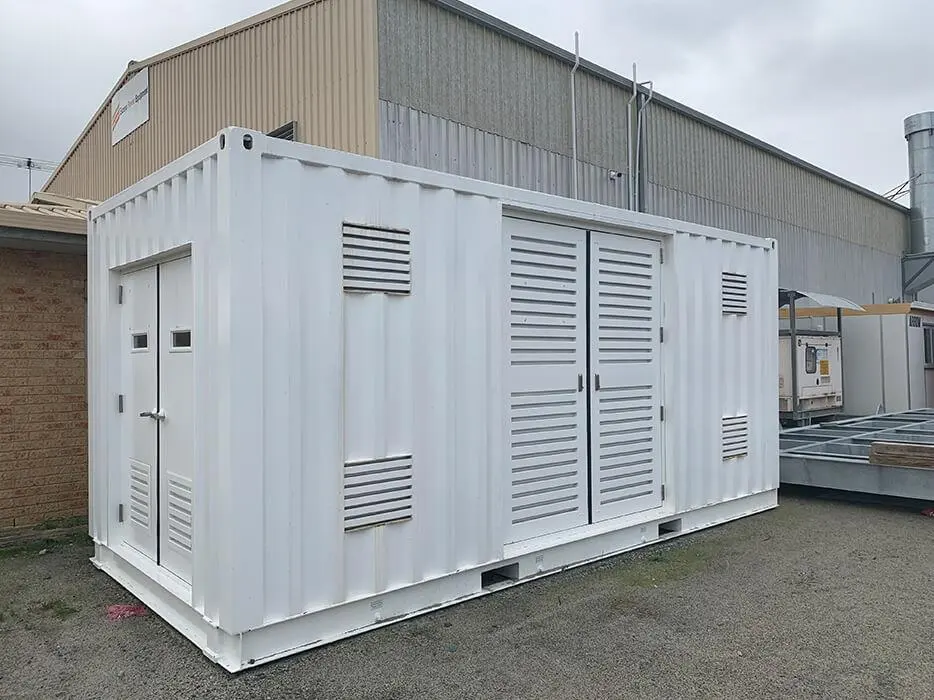
White equipment shelter with louvred ventilation

1 / 2 · Equipment shelter

03

Technical Equipment Shelters

Protective Enclosures for Essential Equipment

Our technical equipment shelters provide dedicated space for machinery, instrumentation and supporting systems. Each shelter can be configured around equipment footprint, service access, heat rejection, utility connections and the environmental conditions of its installation site.

Typical applications: Instrumentation enclosures · Utility equipment shelters · Pump-system shelters · Project-specific equipment packages

Size options

Base formatExternal dimensions: L × W × HTypical layout approach
20 ft standard6,058 × 2,438 × 2,591 mmCompact equipment package
40 ft standard12,192 × 2,438 × 2,591 mmLonger equipment arrangement
40 ft high cube12,192 × 2,438 × 2,896 mmAdditional nominal equipment clearance
Custom-built shelterAs designedEquipment-specific footprint, height and openings
Detailed technical specifications
ItemTechnical specification / configuration
Main structureEngineered steel frame sized for equipment and site loads
Structural materialGrade and member sizes established through design
WallsInsulated or non-insulated weather-resistant enclosure
RoofDesigned for site exposure and required drainage
Floor / baseSized for equipment weight, point loads and maintenance loading
Equipment mountingEngineered skid, plinth or support frame
Access doorsSized for personnel and equipment movement
Maintenance accessRemovable panels or service openings where required
VentilationAir inlets, outlets and fans selected from equipment requirements
HVACWhere required, sized from equipment heat rejection and design conditions
Electrical supplyVoltage, phase and connected load according to the equipment package
LightingInternal and external lighting as specified
Cable entriesLocated and sealed for the selected cable arrangement
Pipe penetrationsDetailed around piping connections and maintenance needs
DrainageProvided where required by the equipment or operating conditions
Noise controlAcoustic treatment where specified
Environmental protectionDust, rain, corrosion and temperature provisions according to site conditions
CoatingSurface preparation and coating system selected for exposure
Transport and liftingBased on final weight, centre of gravity and approved handling method
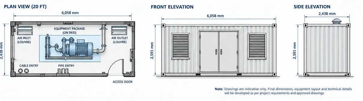
Technical equipment shelter: indicative plan view, front elevation and side elevation of a 20 ft unit
Drawings are indicative only. Final dimensions, equipment layout and technical details will be developed as per project requirements and approved drawings.

Let's Discuss Your Project

The Right Technical Space Starts with Your Requirements

Planning an electrical room, workshop or equipment shelter? Share your intended application, equipment details and required dimensions with our team to discuss a suitable modular configuration.